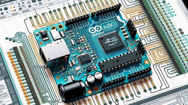
PCB Design: Make Arduino Nano using Altium Designer
- Description
- Curriculum
- FAQ
- Reviews
>>> Learn Printed Circuit Board design by Making Arduino Nano in Altium Designer Software. <<<
>>> Continues Updates <<<
More Than 4000 STUDENTS!!! THANK YOU!!!
What students are saying:
Arshdeep Malik says, “Excellent, very helpful, value for money.”
Zain Ul Haq says, “I learned to work with Altium designer that had once perceived as complex software to use. After taking this course I’m confident to work on Altium designer.”
Why you should take this course?
-
Get the skills you need to become a professional PCB designer.
-
Learn how to design and layout your own Printed Circuit Boards using Altium Designer software.
-
Create Arduino Nano in Altium Designer software and then build it on a development platform (Nano board and Development Tool).
-
Successfully set out, create, and edit your own PCB layout projects in Altium Designer software.
-
Learn the latest industry standard tools and techniques for designing Printed Circuit Boards (PCBs).
-
The course is suitable for beginners who want to get the skills they need to become a professional PCB designer.
Welcome to this course.
What is this course about:
In this course, you will learn from start to finish, from zero to production ready on how to design a custom Arduino Nano Printed Circuit Board. It will help you improve your PCB design skills, which will help you get started freelancing or get a job in PCB design with Altium Designer since it’s the most used PCB design tool.
What you should expect after taking this course:
-
Get started with PCB design using Altium Designer.
-
Download and install Altium designer.
-
Create your own component library to create components that you don’t have a library for, which will help you freelance online since many jobs ask to create component libraries.
-
Create the Arduino Nano Schematic in Altium designer.
-
Wire components in Schematic view.
-
Transfer the schematic into PCB.
-
Place components on the board.
-
Create a multilayer board.
-
Route layers and place components on the board.
-
Autoroute to save time.
-
Eliminate design errors.
-
Create Gerber files for your manufacturer.
What You Will Learn:
-
Design custom Arduino Nano PCBs from scratch using Altium Designer.
-
Develop skills in creating component libraries and schematic designs.
-
Transfer schematics to PCB and create multilayer boards.
-
Utilize autorouting and error elimination techniques.
-
Generate Gerber files for manufacturing.
Who is This Course For:
-
Beginners interested in PCB design.
-
Hobbyists and enthusiasts wanting to create custom PCBs.
-
Aspiring freelancers and professionals aiming to work in PCB design.
-
Anyone interested in learning Altium Designer for PCB projects.
Requirements:
-
No prior experience required.
-
Basic knowledge of electronics is helpful.
-
Willingness to learn and apply new skills.
About the Instructor:
Educational Engineering Team
Team of Skilled Engineers Sharing Knowledge with the World
Educational Engineering Team is a leading entity in the Microcontroller industry with over 13 Years of Experience in teaching and practical projects. We provide in-depth, step-by-step blueprints on taming complex topics in easy and digestible bite-sized videos.
Having been in the Programming and Microcontroller business since 2007, we’ve catered to students’ and educators’ needs, teaching over 250k-THOUSAND students and counting through our 100+ courses on Udemy.
Ashraf Said AlMadhoun is an educator, Mechatronics engineer, electronics and programming hobbyist, and Maker. He is the Chief Educational Engineer at Educational Engineering Team, a company founded to explore new trends and technologies and to educate the world.
Our online courses have helped over 250,000 people globally to excel and make great careers in the industry.
Educational Engineering Team offers Courses on:
-
Circuit Design, Simulation, and PCB Fabrication
-
Arduino, PIC Microcontroller, and Raspberry Pi
-
Programming in C, Python, and other programming languages
-
PLC Industrial Programming and Automation
-
3D Design and Simulation
-
ESP and IoT World
-
5Create Component Symbol & Add PinsVideo lesson
-
6Finishing the SchematicVideo lesson
-
7Creating Your Componenets Symbol - Making Footpring and PCB LayoutVideo lesson
-
8Link footprint with Schematic LibraryVideo lesson
-
9Adding the new Library File to your DesignVideo lesson
-
10Creating the Atmega Component SymbolVideo lesson
-
11Creating the Atmega PCB FootprintVideo lesson
-
12Adding Components and Placing them on SchematicVideo lesson
-
13Adding Components LibrariesVideo lesson
-
14ATMEGA Schematic ConnectionVideo lesson
-
15USB Connector SchematicVideo lesson
-
16Header Pins for Nano BoardVideo lesson
-
17Adding Resistors LED Indicators Voltage RegulatorVideo lesson
-
18Annotating and Compiling ProjectVideo lesson

External Links May Contain Affiliate Links read more


