Mastering SOLIDWORKS (2024-25): A Complete Course

- Description
- Curriculum
- FAQ
- Reviews
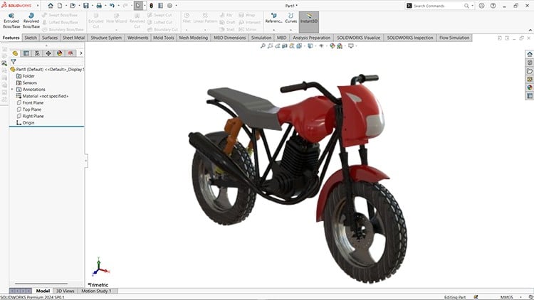
SolidWorks Mastery: Design, Assemble, and Draft a Complete Bike
Unlock the power of SolidWorks with this comprehensive course designed to take you from beginner to expert. Whether you’re a student, professional, or hobbyist, this course will guide you step-by-step through designing bike parts, assembling components, and creating detailed drafting models for manufacturing.
What You’ll Learn:
-
Sketching: Learn sketching tools to create 2D profiles and dimensioning and applying constraints to control sketch geometry.
-
Part Design: Master the art of designing bike components such as frames, wheels, gears, and more.
-
Surfacing: Master the art of designing components using the Surfacing tools.
-
Assembly: Learn advanced techniques to assemble the bike components seamlessly.
-
Drafting: Create professional 2D drawings for manufacturing with precise dimensions and annotations.
-
Industry Techniques: Understand best practices for efficient modeling and real-world applications.
Course Highlights:
-
Hands-on projects with real-world bike design examples.
-
Clear, concise lessons tailored for all skill levels.
-
Practical exercises to reinforce your learning.
-
Access to all project files and resources.
Who Should Enroll:
-
Engineers and designers aiming to enhance their CAD skills.
-
Students preparing for academic or professional projects.
-
Hobbyists looking to explore the world of mechanical design.
Join us and start your journey toward SolidWorks mastery. By the end of this course, you’ll have the confidence and skills to bring your designs to life. Whether you’re an engineer, designer, student, or hobbyist, this course equips you with the skills to confidently use SolidWorks for professional or personal projects.
Enroll now and transform your ideas into reality!
-
2
 Designing the Front Axle
In this tutorial, you'll learn to create a front axle using SOLIDWORKS. We'll use the Extruded Boss/Base tool to build the axle's features and add cosmetic threads with an ANSI Metric machine thread type for a shaded display. All dimensions are in millimeters. By the end of this video, you'll have a complete front axle model ready for your project.
-
3
Modeling the Disc Plate
In this tutorial, you'll learn to create a Disc Plate using SOLIDWORKS. We'll start with the Extruded Boss/Base tool, followed by the Extruded Cut, Circular Pattern, and Fill Pattern tools to complete the Disc Plate features. All dimensions are provided in millimeters. This tutorial is expected to take about 25 minutes.
-
4
Creating the Rim
In this tutorial, you'll learn to create a Rim using SOLIDWORKS. We'll start with the Extruded Boss/Base tool to create the basic cylindrical shape, followed by Revolve Boss/Base for the main body. Then, we’ll use tools like Extruded Cut, Fillet, Chamfer, and Circular Pattern to design the spokes and other features typical to a rim. Finally, we’ll refine the design with Draft and Mirror commands to achieve symmetry and detail.
All dimensions will be provided in millimeters, and this tutorial is expected to take about 45 minutes to complete.
-
5
Designing the Tire
In this tutorial, you'll learn to create a Tire using SOLIDWORKS. We’ll start with the Revolve Boss/Base tool to create the tire’s basic circular profile, setting up its diameter and thickness. Then, we’ll add details using Extruded Cut and Offset to create grooves and treads that improve grip.
We'll also explore the Circular Pattern tool to replicate tread patterns around the tire and the Fillet tool to soften edges for a realistic look. This tutorial will take approximately 30 minutes, and all dimensions are in millimeters.
-
6
Designing the Caliper Piston
In this tutorial, you’ll create a Caliper Piston in SOLIDWORKS. We’ll start with Extruded Boss/Base for the cylinder shape, then use Extruded Cut to hollow it out. Finally, Fillet and Chamfer tools will add smooth edges.
Estimated time: 20 minutes. All dimensions in millimeters.
-
7
Creating the Caliper Pad
In this tutorial, you’ll create a Caliper Pad in SOLIDWORKS. We’ll begin with the Extruded Boss/Base tool to form the pad’s main shape, followed by Extruded Cut to add slots or grooves. Fillet will smooth edges for realistic detailing.
Estimated time: 15 minutes. All dimensions in millimeters.
-
8
Modeling the Caliper Body
In this tutorial, you’ll create a Caliper Body in SOLIDWORKS. We’ll start with the Extruded Boss/Base tool to form the basic shape, followed by Cut-Extrude for the piston cavities and mounting holes. Fillet and Chamfer tools will be used to smooth edges and add realism.
-
9
Designing the Fork Tube
In this tutorial, you’ll create a Fork Tube in SOLIDWORKS. We’ll begin with Revolve Boss/Base to create the main cylindrical shape, followed by Extruded Cut for holes or grooves as needed. Fillet will be used to smooth the edges.
-
10
Creating the Fork Cap
In this tutorial, you’ll create a Fork Cap in SOLIDWORKS. We’ll start with Revolve Boss/Base to form the main cap shape, then use Cut-Extrude for grooves or wrench slots. Fillet will be applied to soften edges
-
11
Modeling the Fork Holder
In this tutorial, you’ll create a Fork Holder in SOLIDWORKS. We’ll start with Extruded Boss/Base to form the holder’s main shape, followed by Cut-Extrude for the fork tube openings and bolt holes. Fillet and Chamfer tools will be used to refine edges for a smooth finish.
-
12
Building the Fork Bodies
In this tutorial, you’ll create Fork Bodies in SOLIDWORKS. We’ll start with Revolve Boss/Base to form the main cylindrical structure, followed by Cut-Extrude to create any necessary holes or slots for functionality. Fillet and Chamfer will be applied to smooth and define edges.
-
13
Designing the Handlebar
In this tutorial, you’ll create a Handlebar in SOLIDWORKS. We’ll start with Revolve Boss/Base to form the main curved shape, followed by Extruded Cut for any necessary holes or mounting points. Fillet and Chamfer tools will be used to smooth the edges for a more ergonomic design.
-
14
Creating the Upper Handlebar Holder
In this tutorial, you’ll create an Upper Handlebar Holder in SOLIDWORKS. We’ll start with Extruded Boss/Base to create the main mounting shape, followed by Cut-Extrude to add bolt holes or slots. Fillet and Chamfer will be applied to smooth edges for a clean finish.
-
15
Modeling the Lower Handlebar Holder
In this tutorial, you’ll create an Upper Handlebar Holder in SOLIDWORKS. We’ll start with Extruded Boss/Base to create the main mounting shape, followed by Cut-Extrude to add bolt holes or slots. Fillet and Chamfer will be applied to smooth the edges for a clean finish.
-
16
Creating the Muffler
In this tutorial, you’ll create a Muffler in SOLIDWORKS. We’ll begin with Revolve Boss/Base to create the main cylindrical shape of the muffler. Then, we’ll use Extruded Cut for creating mounting holes or exhaust openings. Fillet and Chamfer will be applied to smooth the edges, and Shell may be used to hollow out the muffler for a realistic design.
-
17
Designing the Swing Arm
In this tutorial, you’ll create a Swing Arm in SOLIDWORKS. We’ll start with Extruded Boss/Base to create the main structural shape of the arm. Then, we’ll use Extruded Cut to add mounting holes and any other features like slots. Fillet and Chamfer tools will be used to round off edges and give the part a clean, smooth finish. Finally, Pattern tools can be used if any features need to be repeated.
-
18
Modeling the Clamp
In this tutorial, you’ll create a Clamp in SOLIDWORKS. We’ll start with Extruded Boss/Base to form the basic clamp shape, followed by Extruded Cut to add the opening or slots for tightening. Use the Hole Wizard to add precise bolt holes, and apply Fillet and Chamfer to smooth the edges for better assembly.
-
19
Designing the Shock Absorber
In this tutorial, you’ll create a Shock Absorber in SOLIDWORKS. We’ll begin with Revolve Boss/Base to create the cylindrical body of the absorber. Then, we’ll use Extruded Cut to create mounting holes and any internal features. The Fillet tool will be used to smooth the edges, and we’ll add Chamfer to define the part’s ends. Finally, Pattern tools can be used if necessary for repeating features like the external grooves or holes.
-
20
Modeling the Shock Absorber Spring
In this tutorial, you’ll create a Shock Absorber Spring in SOLIDWORKS. We’ll start by using the Helix and Spiral tool to define the spring's shape and coil parameters (diameter, pitch, and height). Then, we’ll apply the Swept Boss/Base tool to create the spring coil. For additional details, we may use Fillet to smooth the spring's edges.
-
21
Creating the Shock Absorber Piston Rod
In this tutorial, you’ll create a Shock Absorber Piston Rod in SOLIDWORKS. We’ll begin with Extruded Boss/Base to form the main cylindrical shape of the piston rod. Then, we’ll use Extruded Cut for any grooves or cutouts that are required, such as the piston cavity or mounting points. We will apply Fillet to smooth sharp edges and Chamfer to define the ends for better fitment with other components.
-
22
Designing the Cylinder Head
In this tutorial, you’ll design a Cylinder Head in SOLIDWORKS. Starting with Extruded Boss/Base for the base geometry, you’ll use Extruded Cut to create combustion chambers, valve openings, and bolt holes. Tools like Swept Cut will form intake and exhaust ports, while Fillet and Chamfer refine edges for functionality and fitment. By the end, you’ll have a detailed cylinder head model ready for assembly or analysis.
-
23
Modeling the Cylinder Head Cover
In this tutorial, you’ll design a Cylinder Head Cover in SOLIDWORKS. We’ll start with Extruded Boss/Base to create the base shape of the cover, followed by Extruded Cut to add bolt holes and recesses. Features like Fillet and Chamfer will refine edges for aesthetics and proper fitment. Finally, we’ll add mounting points, ribs, or patterns to complete the detailed cover, ready for assembly.
-
24
Crafting the Crank Case Cover
In this tutorial, you’ll design a Crankcase Cover in SOLIDWORKS. Starting with Extruded Boss/Base, we’ll shape the main profile of the cover. Extruded Cut will be used for bolt holes, gasket grooves, and any access points. Tools like Fillet and Chamfer will refine edges for durability and fitment. Finally, we’ll add ribs, mounting features, or patterns to finalize the detailed model, ready for integration.
-
25
Creating the Front Mudguard
In this tutorial, you’ll design a Front Mudguard in SOLIDWORKS. Using Extruded Boss/Base and Sweep, we’ll create the curved profile of the mudguard. Extruded Cut will define mounting holes and cutouts, while Fillet will smooth edges for aesthetics and safety. Finally, we’ll add surface details or ribs to enhance strength and style, completing a functional and visually appealing model.
-
26
Designing the Rear Mudguard
In this tutorial, you’ll design a Rear Mudguard in SOLIDWORKS. We’ll start with Extruded Boss/Base and Sweep to create the curved base profile. Extruded Cut will define mounting points and cutouts, while Fillet and Chamfer will refine edges for a smooth finish. Additional features like reinforcement ribs or surface details will be added to complete a robust and functional rear mudguard design.
-
27
Modeling the Fuel Tank
In this tutorial, you’ll design a Fuel Tank in SOLIDWORKS. Starting with Extruded Boss/Base and Loft, we’ll shape the tank’s main body. Extruded Cut will be used for openings like the filler cap and mounting points. We’ll refine the design with Fillet and Chamfer for smooth edges and add features like grooves or ribs for structural integrity, resulting in a functional and stylish fuel tank model.
4o
-
28
Crafting the Headlight Mask
In this tutorial, you’ll design a Headlight Mask in SOLIDWORKS. We’ll begin with Extruded Boss/Base to create the main shape of the mask. Using Swept Boss/Base and Extruded Cut, we'll define the contours for the headlight opening and any mounting features. Fillet and Chamfer will be applied to smooth edges and improve fitment. Finally, we’ll add details like ribs or patterns to enhance strength and finish, creating a fully functional headlight mask.
-
29
Designing the Seat Cover
In this tutorial, you’ll design a Seat Cover in SOLIDWORKS. We’ll start with Extruded Boss/Base to shape the base of the cover. Using Loft or Sweep, we’ll create the contour to fit the seat’s shape. Extruded Cut will define any mounting points or cutouts. Fillet and Chamfer will be applied to smooth edges for comfort and fitment. Finally, we’ll add surface details and reinforcement ribs to complete the seat cover design.
-
30
Designing the Weldment Structure and Frame
In this tutorial, you’ll design Weldment Structural Frames in SOLIDWORKS. We’ll begin by creating a new Weldment part and selecting the appropriate profile for the frame components. Using Structural Member, we’ll place beams and columns to form the basic structure. Mitered Cuts will be applied to joints, and Weld Beads will be added to simulate welds. Fillet and Chamfer can be used to refine sharp edges, and we’ll add any additional features like gussets or braces for added strength. Finally, the frame will be ready for assembly or further analysis.
-
31
Crafting the Seat Assembly
In this tutorial, you’ll design a Seat Frame in SOLIDWORKS. We’ll begin by creating a new Weldment part and selecting the appropriate profiles for the frame structure. Using Structural Member, we’ll place the main frame components, such as the base, side supports, and crossbars. Mitered Cuts will be applied at joints, and Weld Beads will simulate the welding process. To refine the frame, we’ll use Fillet and Chamfer for smooth edges, adding any necessary mounting points or reinforcements. Finally, the seat frame will be ready for assembly or further design integration.
-
32
Brake Subassembly
In this tutorial, you’ll learn how to assemble a brake system in SOLIDWORKS using Assembly Mode. We’ll start by importing components such as the brake disc, caliper, pads, and mounting brackets. Using Mate Tools, we’ll align and position the parts accurately, applying Concentric and Coincident Mates for proper alignment. Key features like Limit Mates will simulate the range of motion for the caliper. Once complete, the brake sub-assembly will be ready for integration into the main bike assembly or detailed analysis.
-
33
Shock Absorber Subassembly
In this tutorial, you’ll learn how to create a shock absorber sub-assembly in SOLIDWORKS. We’ll start by importing key components such as the spring, damper, piston rod, and mounting brackets. Using Mate Tools, we’ll align and connect these parts accurately, applying Concentric and Coincident Mates for proper functionality. To simulate real-world behavior, Limit Mates and Mechanical Mates will be used to define motion constraints. Once assembled, the sub-assembly will be ready for integration into the main assembly or further refinement.
-
34
Motorcycle Assembly
In this tutorial, you’ll learn how to assemble a bike in SOLIDWORKS using the Assembly Mode. We’ll begin by importing individual components, such as the frame, wheels, handlebars, and seat. Using Mate Tools, we’ll precisely align and connect the parts, ensuring accurate positioning. Advanced mates like Concentric, Distance, and Mechanical Mates will be applied for realistic assembly and motion. Once complete, the bike assembly will be ready for further design integration, motion analysis, or rendering.
-
35
Creating Drawing Views - Part 1
In this tutorial, you’ll learn how to create professional drawing views for a rim in SOLIDWORKS. We’ll begin by generating a new drawing file and setting up the appropriate template. Using the View Palette, we’ll add standard views like Front, Top, and Isometric to showcase the rim’s design. Key dimensions, annotations, and details such as section views will be included for manufacturing clarity. Finally, the drawing will be prepared for export in formats like PDF or DWG for documentation or sharing.
-
36
Creating Drawing Views - Part 2
In this tutorial, you’ll learn how to generate detailed drawing views for a bike assembly in SOLIDWORKS. We’ll start by setting up a new drawing file with the appropriate template. Using the View Palette, we’ll insert key views such as Front, Side, and Isometric, highlighting the overall structure of the bike. Detailed views and section views will be added to focus on critical areas like joints and fasteners. We’ll also include a Bill of Materials (BOM) and annotations to document all components. Finally, the drawing will be prepared for export in formats like PDF or DWG for further use.