Fundamental of PN Junction Diode - Application Point of View

- Description
- Curriculum
- FAQ
- Reviews
Hi Friends,
Are you Preparing for Interview in Electronics? Don’t be stressed, take our PN Junction Diode- Application Point of View Course and prepare yourself for your Interview. After resistor, capacitor and Inductor one of the most widely used electronic components is the PN junction diode. Here you Learn the use of PN Junction diode in Different Application Such: Rectifier, Clipper, Clamper and Multiplier Circuit. PN Junction diode is a basic component in electronics, so it is necessary for every students that he learn the Basic Concept of PN Junction Diode. In this Course You Will Learn the Application of PN Junction Diodes and take the first leap to the world of Electronics.
This Course will Covers following Application of PN Junction Diode:
- What is the use of Rectifier Circuit ?
- Working of Half Wave Rectifier.
- Working of Full Wave Rectifier.
- Working of Full Wave Bridge Rectifier.
- Ripple factor of Rectifier Circuit.
- What is the Clipper Circuit ?
- Positive Clipper Circuit.
- Negative Clipper Circuit.
- What is the Clamper Circuit?
- Positive Clamper Circuit.
- Negative Clamper Circuit.
- What is the use of Voltage multipliers Circuit.
In This Course we explain every topic in Simple and Easy Way.
Feel free to reach out if you have any additional questions in PN Junction Diode- Application Point of View Course. Also this course has 30 days money back guarantee without any delay the applicants participate in this Course
All the best for your learning journey of Application of PN Junction Diode !
Cheers!
Harish Kumar Maheshwari
-
2
 Rectifier Circuits: AC to DC conversion
Rectifier Circuits: AC to DC conversion
Role of different circuit components
Transformer:
Step down AC voltage amplitude to the desired DC voltage (by selecting an
appropriate turn ratio N1/N2 for the transformer)
Isolate equipment from power-line
Rectifier:
converts an ac input to a unipolar output
Filter:
convert the pulsating input to a nearly constant dc output
Regulator:
Reduce the ripple of the dc voltage
-
3
Half wave Rectifier
In positive half cycle, D is forward biased and conducts. Thus the output voltage is same as the input voltage. In the negative half cycle, D is reverse biased, and therefore output voltage is zero.
PIV= Vs
-
4
Full Wave Rectifier:
In the first half cycle D1 is forward biased and conducts. But
D2 is reverse biased and does not
conduct. In the second half cycle
D2 is forward biased, and conducts
and D1 is reverse biased.
PIV= 2Vs-VD
-
5
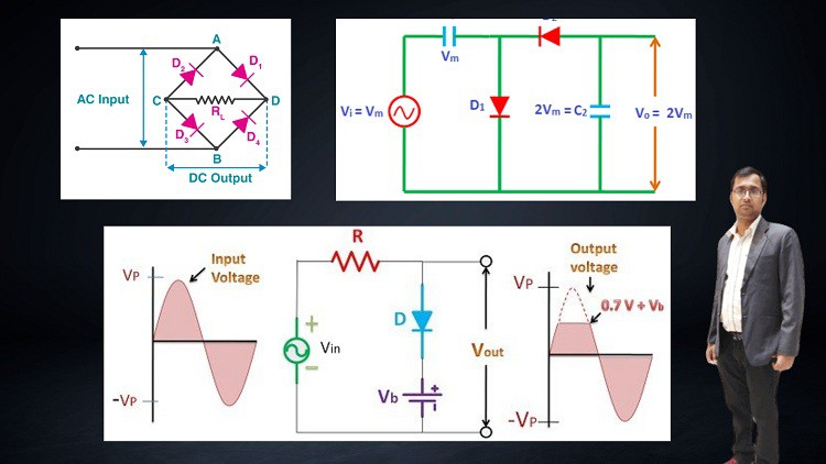
Full Wave Bridge Rectifier:
Current always flows in one direction through the load resistance R,
regardless of whether vS is positive or negative.
In the positive half cycle, D1 & D2 are forward biased and D3 & D4 are
reverse biased. In the negative half cycle, D3 & D3 are forward biased, and D1
& D2 are reverse biased.
-
6
Ripple factor of diode rectifier
The effectiveness of a rectifier depends upon the magnitude of ac
component in the output; smaller the ac component, the more effective is the
rectifier.
Ripple factor is a measure of effectiveness of a rectifier circuit and
defined as a ratio of rms value of ac component to the dc component in
the rectifier output.
-
7
Clippers Circuit
Clippers are the circuit that employ diodes to remove a portion of an input
signal without distorting the remaining part of the applied waveform.
A clipper can serve as a protective measure, preventing a signal from
exceeding the clip limits.
A practical application of a clipper is to prevent an amplified speech signal from
overdriving a radio transmitter. Over driving the transmitter generates spurious
radio signals which causes interference with other stations. The clipper is a
protective measure.
-
8
Clampers Circuit
Clamping is a process of introducing a dc level into a signal.
Clamper circuit consist of diode and capacitor that shifts the input waveform to
different dc level without changing the appearance of the applied waveform.
When the diode is forward biased, it will
conduct and charge the capacitor. The output
voltage across the diode is zero (0.7V).
The capacitor is charged to peak input
voltage quickly because of small time
constant of the circuit.
During the –ve cycle when diode is reverse bias, the diode becomes to its
off state. In this case, the output voltage equals to the sum of the input
voltage and the voltage across the terminals of the capacitor which have the
same polarity with each other
-
9
Voltage Multipliers Circuit
Voltage Multipliers:
Voltage multipliers are the circuit which provide a dc output that is
multiple of the peak input ac voltage.
Voltage doubler will provide a dc output that is twice the peak input ac
voltage and voltage tripler will provide a dc output that is three times the
peak input ac voltage.
The basic idea in voltage multiplier circuit is to charge each capacitor to
the peak input ac voltage and to arrange the capacitor so that their stored
voltages will add.
Voltage doubler:
During the positive half cycle, diode D1 is forward biased and diode D2 is
reverse biased, that will charge capacitor C1 to peak value of input voltage.
During the negative half cycle, diode D2 is forward biased and diode D1 is
reverse biased, that will charge capacitor C2 to the twice the peak value of
input voltage because capacitor C1 ( charged to Vp) and input voltage (Vp )
now act as series aiding voltage source.
When input voltage returns to its original polarity, diode D2 is again reverse
biased (off), and then the capacitor C will be discharged through the load R
The time constant (RLC2) is so adjusted that C2 has little time to loose any
of its charge before the input polarity reverses again.
During the negative half cycle, diode D2 is turned on , capacitor C2 will be
recharged again until voltage across it is again equal to 2Vp.
-
10
 QUIZ
QUIZQuiz of the Course.